|
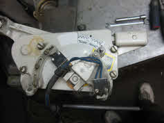
- OMC 400 and 800 shift cable adjustment from shifter housing located on top of intermediate housing inside engine
compartment
- Exploded view 400 and 800 tech drawings or lower unit
- Step by step removal pictures and tools required
- See shift rod setting and warning before installing.
|
|
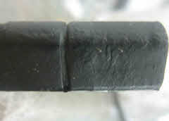
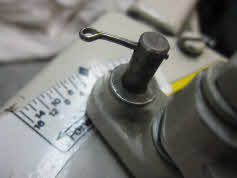
A1 cable with one grove 1978-1981
|
1978 to 1981 shift cables have one ring on end of cable. Some 1978 units have no ring on end there just plain.
These unit have a fixed rod in them attached to a servo hydraulic shifter and there is no adjustment in gearcase.
|
|
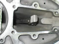
A2b 1978 to 1981 lower unit gearcase
|
OMC gear-case years 1978 to 1981 has no shift rod adjustment in them. They have hydraulic shift assist built in and do
not have square cut out for anode. See figures D2 and D3 that have cut out in the gear-case.
|
|
A3 OMC 400-800 shift cable Note flat top on shifter end 1978-1985
|
When installing shift cable you need to make sure you line up flat section with brass spring loaded receiver during
installation. Rubber need to be full and not soft or deformed or spring tension on wires will be incorrect or to loose. If
wire doesn't have correct tension the ideal pullers in lower unit will jam and stop wire from engaging into forward gear.
This is common on cables where rubber has gone soft due to composition of material and oil leaking from outdrive
that has been stored in the up position. Water leaking into lower unit will also force oil to travel up the cable.
|
|
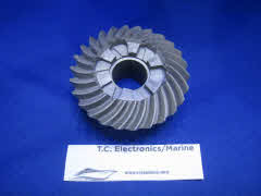
A6 Reverse-forward gears lug area can not be worn
|
Worn lugs on forward or reverse gear will stop clutch dog from going into gear properly. This is usually a sign that
engine ideal speed is not at the correct RPM. This happens over time say 50 to 100 shifts at 700 or 900 RPM way to high. Gears
should be engaging at 550 or 625 RPM maximum.
|
|
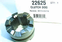
A7 Clutch dog lugs area can not be worn 1982-1985
|
Clutch dog (part 914716) should be replaced when lugs are rounded off. Steel on clutch dog does not have the same hardness
as the forward or reverse gear and often need to be changed do to normal ware. Note there is a 3 and 5 degree clutch dog and
gears with the 5 degree being the newer units.
|
|
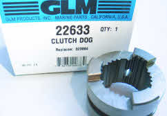
A8 Clutch dog engagement speed
|
This is a four cylinder clutch dog with only 3 lugs.
Clutch dog engagement speed for four cylinders needs to be between 550 and 675 RPM.
|
|
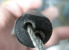
D1 end will have two groves 1982-1985
|
This 1982 to 1985 Shift cable with two rings and is not interchangeable with the 1978 to 1981 if you do the
unit will work in reverse.
|
|
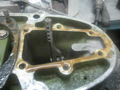
D2 800 lower unit gearcase with anode cut out
|
The straight mechanical shift lower unit gearcase years 1982 to 1985 has anode cut out hole. The servo hydraulic gearcase
does not have an anode cut out.
|
|
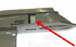
D3 1982-1985 Mechanic shift identification
|
Arrow show cut out area of 1982 to 1985 outdrive. This is easiest way to tell what the year of your 400 and 800 outdrive.
|
|
D4 Thread Rod In Six Turns
|
Adjustable rod and rack end (should be set at 6 turns) OMC shift cable end will have two groves years 1982 to 1985.
|
|
D5 Rack and shifter rod setting is 6 turns
|
If you have threaded shifter rod all the way down outdrive will be out off adjustment range.
Some manuals I have seen
do not list this information any where and and boating enthusiast will need to do repair all over again.
|
|
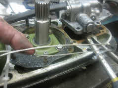
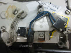
D6 Rack shifter rod installed
|
Shifter housing must be removed to adjust threaded rod.
|
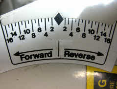
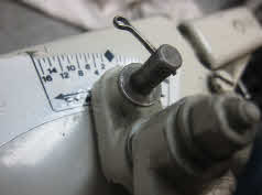
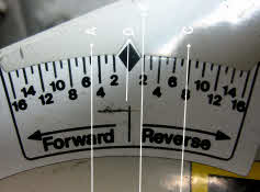
Shift cable in neutral position |
Record shifter arm neutral position before starting adjustment as setting may not line up with gauge on sticker
|
|
E1 Record arm neutral position
|
|
|
E3 Shifter arm in forward position
|
Shifter arm with shift cable in forward position
|
|
E4 Shifter arm in neutral
|
Shifter arm with shift cable in neutral position. Note neutral position should correspond to the lower unit clutch dog having
equal space between forward gear and reverse gear.
|
|
|
Shifter arm with shift cable in reverse position
|
|
H1 Adjustments will require boat to be in water
|
Final shift adjustments need to be done with boat in the water and some propeller resistance.
|
|
|
New Forward-Reverse Settings
|