This newsletter section is not intended to replace a repair manual, but rather aid to reduce the amount of time it takes
you to make your repair. The following is for OMC cobra lower gear cases 3L to 5.8L. It is taken for granted that at this
point the lower gear case will be separated from the upper gear case, I will try to write instructions in a step by step format.
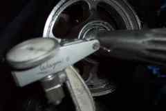
If water is entering your lower unit one of the probable causes could be a worn propeller shaft
and the seal could be worn due to a bent prop the characteristics are the more it is bent the faster the seal would wear out.
The prop shaft should be replaced if over .003, you can put a dial indicator on it and turning it to determine if is bent.
If prop shaft has only bearing play and is not out of round just by changing bearing in most cases will reduce play in carrier
to shaft.
Undo shifter by turning counter clockwise, count the amount of turns that it takes
to come loose. Once it comes loose (you do not remove it) you only undo it until it lifts up about 1 or 2 inches then tape
in place using electrical tape on shaft to hold shaft from dropping down. Note if you lose count or wish to place back to
factory settings, main case to top of shifter in neutral position should be 7.156 " using dial caliper try to stay within
plus or minus 1 turn.
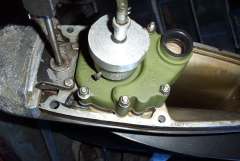
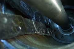
Remove carrier undo 4 bolts inside on some models and just a tab on others
#71 on our drawing. Use puller # 90095 to pull out carrier. Note in some cases heat must be used on carriers from salt water.
Normally a propane torch is enough heat, place 1" from carrier area around the main case.
Next
step would be to remove the water passage housing item #15 part # 27760 clean and remove old gasket. Note replace gasket,
gasket comes with seal kit #87656. Next remove housing part #27770, # 22 on layout drawing, undo the 4 bolts and pry the unit
out. Note replacement o ring comes with seal kit #87656.
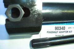
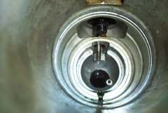
Remove pinion nut on the bottom of
the drive shaft. Can use tool # 90340, slide onto unit to hold nut in place and stop it from turning. Then using ( tool #
90350 adaptor ) to turn the drive shaft counter clockwise to undo the nut. Note do not take the drive shaft all the way out.
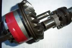
Lift drive shaft, once you take the nut out from inside by prying shaft up then pull the pinion gear out with a magnet. The
drive shaft then gets lifted but only lifted high enough to remove the pinion gear, do not take the drive shaft all the way
out. Once the pinion gear has been removed and the drive shaft lifted just high enough to clear the forward gear then the
prop shaft can be pulled out of the unit as a complete assembly.
When the complete assembly
is pulled out of the unit get some electrical tape and place it around the bearing carrier assembly so that the shift pin
that holds the lever stays in place. Once the tape is in place the spring can be taken off the clutch dog and the pin that
goes through the the clutch dog can be taken out at which time the shaft can be pulled straight out and leave the assembly
all in tact. The spring on the clutch dog can be removed by simply inserting a screw driver and prying it over the clutch
dog area. It is not required that the spring be completely removed only removed enough to take the clutch dog pin out.
At this point care should be taken that the clutch dog direction or end do not get mixed up. Now install propeller
shaft in same fashion as old one was taken off. The prop shaft, forward gear, and carrier assembly are then placed into the
case and firmly put into position. Note that the pin on carrier should line up with the slot inside the cavity of the column
in case.
At this point the pinion gear should be in place. I have preference to using magnets
to install the drive shaft while rotating tool clockwise in such a fashion that to find the slots or splines in pinion gear
and push through.
Our special tool with the nut inserted in it will slide into the unit and tool on top is used
to tighten the nut back up. Use loctite solution on the nut prior to installing it in the tool slot. Should be noted that
reverse gear then thrust washer that holds the retainer in should be placed in front of the 2 snap rings. It's a common error
to place it in the middle of the 2 snap rings.
Note that on the GLM seal kit #87656 that is used for the above
process to change the seals or o-rings the offset seals included can be used as it will aid in using older worn shafts. Place
offset seal to locate on clean area on older surfaces that have no scoring on it.
Numbers given above
are aftermarket OMC outdrive parts by GLM