Cobra sterndrive *800 OMC parts *Mercruiser outdrive videos
OMC 400-800 Lower unit repair steps 21-40
400-800 series installation / repair steps for lower unit.
400-800repair photosCo-manufacturer and distributor for GLM Products including aftermarket with 2 year warranty on parts
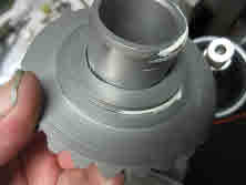
Reverse gear and bearings
Gears are installed into housing
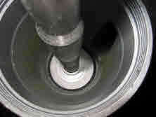
Thrust bearing
Retainer plate
Circlips
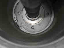
Retaining circlip is installed
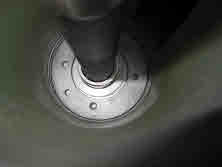
Plate holes lined up
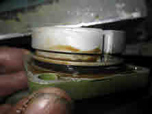
Gasket compound
Gasket sealing compound is applied to the end of the bearing carrier
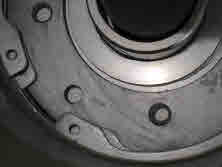
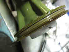
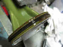
O ring gasket compound
The o-ring (GLM P/N 82400, replaces 305123) is installed onto the carrier
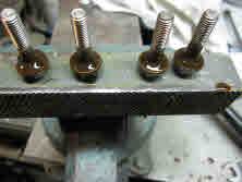
1/4 inch 28 N.F. thread bolts
Bolts are prepared with compound
Bolts with compound
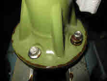
Bolts are installed into the carrier
Carrier bolts installed
Bearing carrier, which has been sandblasted, primed with bearings installed is then set into the lower unit to secure the propeller shaft
Anode installed
Rear anode is installed (GLM P/N 12776, replaces 436745)
Bearing shims
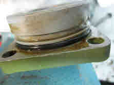
O ring
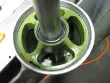
Bearing is pressed into housing
Retainer
Bearing housing (OMC 982422), is sandblasted, primed and the o-ring is installed with sealing compound
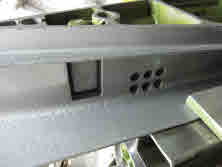
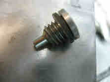
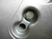
Magnetic screw
Oil plug / drain screw (GLM P/N 21731, OEM 318544) is installed into the lower unit with the plug gasket
Anode bolt added
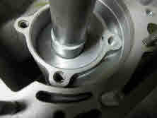
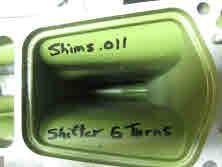
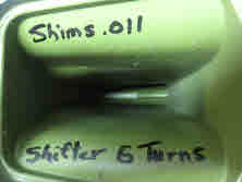
Note shim size
Note shifter turns
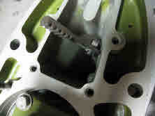
See rack position
Shifting rod, rack and components are installed and set up
*800 series and Cobra lower unit drawing.Click here for steps 41 - 50 in the rebuild process
T.C. Electronics/Marine (416) 751-7326Copyright 2002 to 2026 all rights reserved